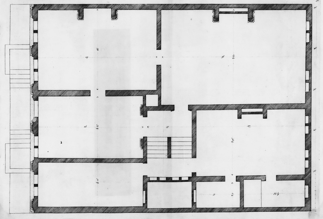
A floor plan is the most familiar architectural drawing, yet many people look at one without fully reading it. It is not a picture of a room seen from above. It is a horizontal slice through a building, drawn to scale, using conventions that tell you what is cut, what lies below the cut, what lies above it, and how everything is dimensioned.
This guide explains how to read a plan systematically, from the title block to the dimensions and notes. It is written for homeowners reviewing a renovation scheme, buyers studying a developer’s brochure and students learning the conventions. We also explain what a plan does not show, particularly about structure, so that you know when to ask for other drawings.
What a floor plan actually shows
Imagine cutting horizontally through a building a little above window sill height, typically around a metre or so above the floor, removing everything above, and looking straight down. That is the convention behind an architectural plan. Walls, columns, doors and windows that are cut by this imaginary plane are drawn with heavier lines. Floors, furniture, fittings and anything below the plane are drawn with lighter lines. Things above the cut that matter, such as a beam, a bulkhead or the edge of a void, are often drawn as dashed lines.
Understanding this cut explains most of what follows. A high window above the cut line might be shown dashed or annotated rather than drawn as an opening. A low wall below it is shown as an outline rather than a solid. Once you read the plan as a slice, the line weights start to make sense.
Start with the title block, scale and north point
Before looking at rooms, read the frame around the drawing. The title block identifies the project, the drawing title, the drawing number, the revision, the date and who prepared it. Always check that you are looking at the latest revision; schemes evolve and older drawings circulate for a long time.
Next, find the scale. Plans are usually drawn at ratios such as 1:100 for a whole floor or 1:50 for more detail, which means one unit on paper represents one hundred or fifty on the ground. Our guide to architectural scale explains how to use these ratios and why you should never scale dimensions from a printed copy that may have been resized. A bar scale on the drawing is more reliable than a ratio once a document has been printed or copied.
Finally, find the north point. Orientation matters in Singapore for sun and rain: west-facing rooms receive harsh afternoon sun, and the direction of prevailing rain affects windows and balconies.
Walls, columns and openings
Walls are the backbone of any floor plan. Cut walls are drawn as two parallel lines, often filled with a solid tone or hatching that indicates material. Thicker walls may be external or structural; thinner ones are often internal partitions. Columns are usually shown as solid squares, rectangles or circles at regular intervals.
Doors
A swing door is drawn as a line for the leaf with an arc showing the swing. The arc tells you which way the door opens and how much clear floor space it needs. Sliding doors are shown as offset lines within the wall, and folding doors as zigzags. Our companion article on floor plan symbols includes a table of these conventions.
Windows
Windows appear as thin lines within the wall thickness, often three or four parallel lines, sometimes with a sill line. Window types and sizes are usually referenced by a tag that links to a window schedule.
Stairs and level changes
Stairs are drawn as a series of treads with an arrow indicating the direction of travel, usually marked up or down from the floor shown. A diagonal break line shows where the stair passes through the cut plane. Steps and level changes elsewhere are noted with spot levels.
Dimensions, grids and levels
In Singapore and most metric countries, dimensions on architectural plans are given in millimetres unless stated otherwise. Dimension strings run along the outside of the plan, usually in layers: overall dimensions, then dimensions between grid lines, then dimensions to openings and walls. Internal dimensions may be given for key rooms.
Larger buildings are set out on a structural grid, labelled with letters in one direction and numbers in the other. The grid is how architects, engineers and contractors refer to locations: a column at B-3, for example. When you discuss a plan with an engineer, grid references avoid confusion.
Spot levels indicate floor heights relative to a datum. Small differences matter: a step down into a bathroom, a raised platform or a fall towards a drain will each be marked. Level changes are a frequent source of renovation problems, particularly when waterproofing and screeds are added.
Rooms, fittings and notes
Rooms are labelled with their intended use and sometimes an area. Kitchens and bathrooms show fixed fittings such as counters, sinks, water closets and showers. Furniture may be shown to demonstrate that a room works, though it is not part of the construction.
Notes and tags link the plan to other documents: finishes schedules, door and window schedules, and detail drawings. A small circle with a number and a sheet reference indicates where a detail or section can be found. Section markers, drawn as lines with arrows across the plan, show where a vertical cut has been taken; our article on section drawings explains how to read them.
If you are looking at a residential plan specifically, our guide on how to read house plans covers bedroom sizes, circulation and the practical layout questions homeowners tend to ask.
What a floor plan does not tell you
An architectural plan is not a structural drawing. It may show walls of different thicknesses, but it rarely tells you with certainty which walls carry load, where beams run, how the slab spans or what is inside a column. Those details are in the structural drawings, which use their own conventions and are prepared and endorsed by the engineer.
This matters most in renovation. A wall that looks like a partition may be load-bearing, and a wall that looks thick may simply contain services. Before removing or altering walls, the structural drawings should be checked and, where needed, an engineer consulted. Our guide to load-bearing walls explains why.
A plan also says little about heights, which is why sections and elevations exist. Ceiling heights, beam depths, window heads and the relationship between floors are all better understood from those drawings. Read the set together rather than relying on the plan alone.
Frequently asked questions
What is a floor plan?
A floor plan is a scaled drawing of a building as if cut horizontally a little above sill height and viewed from above. It shows walls, openings, rooms, fittings and dimensions on one level.
What scale are floor plans drawn at?
Common scales are 1:100 for a whole floor and 1:50 for more detail, with larger scales for specific areas. Always use the stated scale or bar scale rather than measuring a printed copy that may have been resized.
Are floor plan dimensions in millimetres?
In Singapore and most metric countries, architectural dimensions are given in millimetres unless the drawing states otherwise. Levels are often given in metres relative to a datum.
Can I tell which walls are load-bearing from a floor plan?
Not reliably. Architectural plans do not consistently distinguish structural walls. Check the structural drawings and consult a qualified engineer before altering any wall.
What do dashed lines on a floor plan mean?
Dashed lines usually represent elements above the cut plane, such as beams, bulkheads, voids or overhead cabinets, or hidden elements below. The drawing’s legend or notes confirm the convention used.
Related reading
- Heydar Aliyev Center by Zaha Hadid: Design and Structure
- Kerry Hill Architects: Tropical Modernism from Singapore
- SCDA Architects: Practice, Approach and Key Projects
- Plot Ratio in Singapore Explained: How URA Uses GPR
Unsure whether a wall on your plan can be removed? Talk to our consultancy or get in touch.